My solution is the "Invisible" Wii Sensor Bar that works well from the couch, turns on and off automatically with the TV and takes up no space under the TV. And by invisible, I mean it is hard to notice from more than a couple of feet away. If you can find a donor USB cable, you only need to add a few inexpensive parts from Radio Shack and do a little bit of soldering. You should be able to complete the project in a couple of hours or less once you have the parts.
(1) USB cable, 1 m (almost any USB cable that will plug into a PC style port)
(2) IR LED diodes
(1) 33 ohm resistor
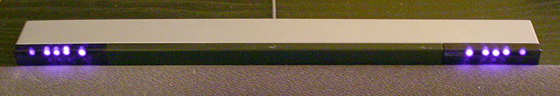
The Wii Sensor Bar is equipped with Infra-Red (IR) Light-Emitting-Diodes (LED's) to allow the Wii remote to orient itself when you point the remote at the TV (with the sensor bar setting on or under the TV). The image below from Wikipedia shows the IR LED's in the Wii sensor bar as seen by an IR sensitive camera. You may be able to see IR LED's using the camera on your cellphone, try both the front facing and rear facing cameras. The Wii Sensor Bar's LED's provide reference points for the IR camera in the remote to determine the orientation of the Wii Remote. It turns out that Sensor Bar is a misleading name as the bar does not actually have any sensors. All of the sensors are actually in the Wii remote.
I tried a battery operated sensor bar but go tired of turning it on and off (there was a loud beeper if you forgot to turn it off) and recharging the battery. It also did not work well from our couch with is about 12 feet from the TV. (Note, do not plug your new DIY sensor bar cable into your TV until you verify the IR LED's light up using some kind of camera. This is covered under Testing below.)
Design
Here is how we make the idea work. A quick web-search reveals that a standard low-power USB devices can draw up to 100mA without requiring any negotiation with the USB host. So to meet the USB spec, a TV's USB port must be able to supply 5V at a minimum of 100mA. So we can treat the TV's USB port as a 5V power supply that can put out 100mA to use to power our project! My next step was a trip to Radio Shack where I looked through the parts bin and found the High-output IR LED's below.
Note that here are many IR LED's that will work well. I would look for 940nm output and avoid anything with a very narrow viewing angle. You set the current with the bias resistor so you can use LED's with higher maximum current but make sure your LED can work at the 100mA range used here or use a larger resistor to set a lower current.
Infrared LED, High-Output, 5mm, (Vf = 1.2v, Imax = 100mA, 940nm, 45-degree)
http://www.radioshack.com/product/index.jsp?productId=2062565


The IR LED's require a forward voltage of 1.2V to turn them on and can handle up to 100 mA. This means I can connect two (for a left and right for the sensor bar) in series for a forward voltage of 2.4 volts. Note that the Wii remote looks for and reports back the 4 brightest spots (LED's) but I found 2 LED's worked fine in my setup. Now I just need to pick a bias resistor to limit the current.
I want a safety margin versus the 100 mA current limit of both the LED's and the USB port. I picked 80 mA as a good starting point and used an LED resistor calculator to determine the best resistor value for the application. http://ledcalc.com/
 The calculation shows 33 ohms (producing 78.8 mA) is the closest standard value (and I picked up a pack at RadioShack, http://www.ittybittyurl.com/2AZx) as well as a nice diagram showing how the LED's will be connected. (I like to connect the bias resistor to the positive supply terminal to limit the short circuit current should any thing below the resistor accidentally short to ground.)
The last part I need is a USB cable that I can plug into the TV and use to get power to the IR LED's. You could use almost any standard USB cable. If the cable is too short, you will simply need extra wire to reach the LED's. I had a very long USB cable from PartsExpress that fit the bill nicely.
Build
First, estimate how long the cable needs to be to reach the LED furthest from the USB port. You may need to search for images of the back of your TV to see where the USB port is located, I know I did. Next strip and prep the far end of the cable for soldering.
I recommend making the black and red wires 3 to 4 inches long and connecting the LED here. I added solid copper extension wires (the green and yellow wires) to my LED's so I could bend the wire to aim them and have the solid wire hold the bend. After installing the finished cable I believe extension wires did not provide any benefit and can be omitted.
You need extra length on the red and black wire to provide room for the heat-shrink tubing to be moved way from the LED terminals when they are soldered. Don't worry, you will know if you get this wrong. Just back up and repeat the soldering.


Note that the yellow wire is connected to the LED has a flat edge on the side where the yellow wire connects. The flat marks the cathode or negative terminal of the LED. So you should connect the black wire to the flat side of the LED and connect the red wire to the other side (where I have the green wire). And then cover the wire with heat-shrink tubing.
So here you will see an LED connected to your red and black wires at the far end of your USB cable.


Next we will decide where to connect the second LED and the current limiting resistor. Now is a good time to shorten the cable to your desired length (do leave a little extra though). I did not trim enough length from the cable and ended up need to take up the slack when I installed the finished project. Decide where you want to put the second LED and cut the cable.

Here I have tried to maintain the convention that the USB end of the cable is to the left side of the image and the LED end of the cable is to the the right side of the image. Note, I recommend stripping the cable so the wires are 3 inches or so and avoiding the extension wires that I used.

Next, twist the stripped end of the red wire (incoming 5V from the USB port) around the resistor lead as close to the resistor as possible. Then solder the wire and trim the excess resistor lead. Then trim and form the other lead of the resistor and add a piece of heat-shrink tubing. I like a hook on the trimmed lead to make it easier to physically attach the wire before soldering.


Now, strip the other cut-end of the cable attached to the first LED and solder the red wire to the remaining resistor lead and cover with heat-shrink. Remember to strip a longer section if you want to avoid using extension wires.


Next, fold the cable back on itself and tape or zip-tie the cable together. The tape or zip-tie acts as a strain-relief to prevent stress on the solder joints. Here the black wire on the left connects to the USB ground. This will connect to the LED flat (cathode). The black wire on the right connects to the cathode of the LED we previously soldered.

Again, I used solid-copper yellow and green extension wires to allow me to pose the LED but feel that there was little benefit. If you stripped enough cable, you can use your longer black wires to connect to the LED. Otherwise you will need to add extension wires.

You should test your cable before adding additional heat-shrink over the bias resistor. It will be easier to debug before the extra heat-shrink. The heat-shrink tubing added after testing will act as a strain-relief and protect your solder joints when installing or adjusting the cable.

Testing
You should verify your cable works BEFORE plugging it into your TV. Use a remote control that you know works (for your TV perhaps!) and find a cellphone camera or digital camera camcorder that will allow you to see the IR LED flicker when you push a button on your remote. On my iPhone the rear facing camera is sensitive to the LED but the forward facing camera is not. Now use a cellphone or other wall mounted USB charger (better to burn up your charger rather than your TV) to power the cable and verify the LED's light up. I know that the USB spec calls for short-circuit protection but I would rather test first with an expendable USB charger. Here is one of my installed LED's as seen by a small point-and-shoot digital camera.

If you see only one LED light up, you probably have a short on the wiring of the OTHER LED. If you see no LED's on, just go back and check for shorts and verify the the polarity on your LED's. Note that getting one LED backwards will prevent either LED from illuminating.

I stripped the extension cable in the middle to allow me to access the power wires. I broke the connection in one power conductor so I could insert a meter and measure current flowing through the cable.

Note that I split the ground wire rather than the 5 volt red wire because and accidental short of the black wire to the cable shield or ground would not cause a problem. An accidental short of the red wire would short the 5 volts to ground and depend on internal protection of the USB port to limit the current.

I measured 66 mA, well under our 100 mA current limit. A short-circuit would have shown current higher than expected and an open circuit or reversed diode would have caused no current to flow. The current is lower than the 78.8 mA expected. So there is clearly some combination of higher diode forward voltage drop, more than 33 ohms in our resistor or a slightly lower USB voltage.

Here is the finished cable. Clearly I could have trimmed out much more extra cable. Initially I expected that having extra distance between the IR LED's would improve the performance at greater distance from the TV. Increased space between the LED's did not help. It appears the original Wii bar LED spacing is near optimal. My desire to experiment with mounting is one of the reasons I left in the extra cable.

Install
Getting the sensor bar to work is easy. Getting it work work well requires a little set-up time. The key steps for my installation and setup were:
- mount the LED's on the edge (top or bottom) of the TV that is closest to the player
- mount the LED about as far apart as the Wii Sensor Bar that came with the Wii
- tilt the LED's slightly to point at the furthest place you will use the Wii remote
- adjust the sensitivity to the highest value that works well at the CLOSEST distance
I used blue painter's tape (removable paper masking tape) to mount the LED's to the bottom of my my TV. I tried several types of tape with poor results. I also I tried top mounting but was not please with the performance. The tape is much harder to see than you would expect. Electrical tape was the next best performing tape.
The LED's worked best when mounted closer together than I expected, close to the spacing of the original sensor bar. The closer you mount the LED's the closer you can stand to the TV and still use the Wii remote. Greater distance between the LED's may be beneficial at distances greater than 12 feet but I did not have the space to test this theory. I mounted the LED's as close together as possible, about 14 inches apart (the limiting factor for me was a center channel speaker sitting directly below the TV).


Try to tilt the LED's toward your furthest player position. For me this was the couch, so I tilted the LED's slight down and slightly inward.
I was surprised at how much effort went into taping the LED's to the TV. It took trying several kinds of tape to find one that would stay on the TV. The stiff extension wires I used worked against me here. I found that painter's tape and electrical tape worked best. Be prepared to try a few kinds of tape to get the best results for your install.
Now you should plug the USB cable into the TV. No go to <Wii Settings> select page 2 of settings and select <Sensor Bar> and then <Sensor Bar Position> and select <Below TV> (or <Above TV> if that is where you mounted yours). Next go to the Wii settings for <Sensitivity>.

Click through until you get the dark screen that shows the LED's as seen by the remote. This is the best screen for diagnosing your set up. Here you can see how the two dots get farther apart as the remote gets closer to the screen as well as how the dots get closer and dimmer as you get farther away from the TV. I found that a Sensitivity of 3 was a good balance between performance at my maximum distance and closer to the TV.
Setting the Sensitivity too high can cause artifacts from internal reflections in the Wii remote when the remote is too close to the TV. Here you can see two smaller dots from internal reflections caused by pointing the remote directly at an LED from a distance of two feet. This is so close the other LED is not visible to the remote.

Increase the Sensitivity to 4 (or even 5) if your pointer is jumpy at your maximum viewing distance (also try tilting your LED's toward your viewing position). Lower the Sensitivity and or move the LED's closer together if your pointer gets jumpy when you are at your closest viewing distance.

I am pleased with the look and performance of the new sensor bar. TV. It turns on and off with the TV and is practically invisible. Here it is installed on the TV and you can just barely see the LED's a couple of inches on either side of the center channel speaker. I have worked on improving the LED attachment using peel-and-stick adhesive and will provide details in a future post.
I had fun building the Invisible Wii Bar and hope you find it useful!
No comments:
Post a Comment