Sam (my Step-Father) has a 1952 Studebaker Champion that he has restored. During one of our too infrequent visits he was showing me his latest work when I noticed a small 12V battery (like you would find in a UPS or alarm system) in the trunk with a cigarette lighter socket attached via a short cable. He explained that the car had a 6V positive ground electrical system and he used the 12V battery to power his GPS when he drives to car events and for charging his cellphone while he is in the car. He said a 12V outlet for the car would be nice and asked if I thought I could build one. Challenge accepted!
 |
| Sam's 1952 Studebaker Champion |
Initially I used electrical tape to insulate the power socket from the metal dash (which is at +6V) so the body of the socket could be connected to battery negative. This allowed the use of boost converter to generate 12V from the 6V battery.
 |
| First attempt insulated the power socket from the 6V positive ground metal dash. |
I considered a fully insulated power socket but could not find one that would fit the existing dash opening. I also considered using a plastic bracket to mount the power socket but that would spoil the factory look the dash. Sam was so kind as to offer to use a pigtail socket that he stows under the seat when not needed but I was determined to find a way to use the existing mounting spot in the dash.
A search of Pololu's DC-DC Boost Converters found no 18 V boost converters but I did find the U3V50 adjustable boost converters. These small module have a 5A input switch and adjustable output (9-30 V) for $17. Notice that these modules are offered in several fixed voltages (but not 18V) and two adjustable voltage ranges. Be sure to get the higher (30V) adjustable range, U3V50AHV. Perhaps Pololu will offer an 18V option in the future.
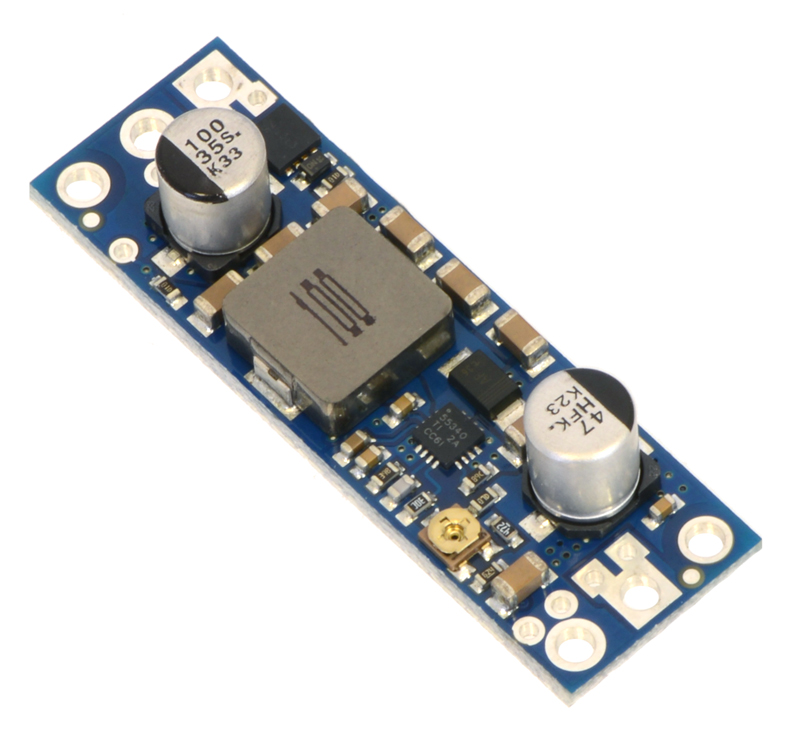
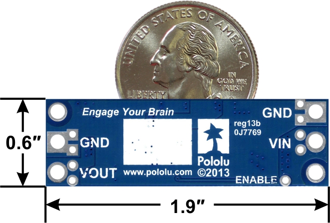
https://www.pololu.com/product/2571
Once I received the module, I added some wires, powered it up and dialed the voltage to 18V. The product page at Pololu has some great information about the module's efficiency. There is even a chart showing efficiency when set for an 18V output with several input voltages.
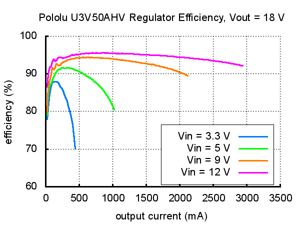
Looking at the chart we can see that a 5V input provides an 18V output at 1 amp at better than 80% efficiency. So our 6V nominal input should give us even higher output and higher efficiency. I tested the module with a USB car charger and a PortaPow USB Power Meter. The image below shows the unit providing over 10W while charging an iPad.
The module got hot before the current started dropping off as the iPad reached full charge but the module never reached the high-temperature cut-off. The Pololu module is very robust but I would not try to draw more than 1 amp from the 12V power socket. So no high power stereos or ham radio rigs. But you should be able to charge your phone or run your GPS all day long.

The Studebaker's existing lighter socket was power via a switched negative wire with a bullet connector on the socket center terminal and an empty spade terminal on the socket body (our positive chassis 6V power source). To make the installation easier, I added a different color wire to each of our module connections and a matching connector for each terminal. I also insulated the module with clear heat-shrink tubing.


Connections:
Blue wire to the power socket center terminal (module Vout)
Green wire to the power socket center terminal (module Vin)
Black wire to switched negative terminal (module GND)
Installing the new module was simple, requiring only unplugging the existing wires from the socket and connecting those wires to the module. So we unplugged the wire from the existing socket center bullet terminal and connected this to the module GND wire. Then we connected the body/chassis wire from the power module to the tab on the light socket (electrically connected to the chassis positive ground via the metal dash). Finally the output voltage wire (boosted to 18V) of the power module was connect the lighter socket center terminal.
After inserting the connectors, the wires were bundled and zip-tied to the firewall. The install only took a couple of minutes. The interior appears stock other than a plastic socket cover that indicates that it is actually a 12V outlet.


The voltage of a conventional 12V automotive system actually vary over a wide range. Wikipedia says that "Equipment intended to be powered by the receptacle needs to account for intermittent contact, and voltages outside the nominal 12V DC, such as maximum voltage 9–16V continuously. To function in this environment, 12V automotive accessories are designed to operate over a wide range of input voltages. For example, the Amazon top selling Schoche reVolt dual USB car charger specifies an input voltage range of 10 to 16 volts.
I measured the output voltage under different engine conditions to get a feel for the range produced by the boost converter on the Studebaker. At key on with the engine not running the socket put out 12.75V. The voltage varies once the engine is running though because the generator output varies with engine speed. The voltage varies because the socket output is actually 18V - generator output voltage. The socket voltage output dipped as low as 11 volts at some engine speeds. The module could be modified to produce a stable voltage difference of 12V but this appears to be unnecessary for the vast majority of applications.
Update
Sam upgraded the install with a matching cigarette lighter plug and socket. He removed the heating coil to keep it from being able to make electrical contact with the power socket voltage.


Conclusion
The module worked with every device tested and has been installed and working in the Studebaker for over four years now. If you want, it is simple to build your own 6V Positive Ground to 12V power socket converter.
1 - Order the Pololu Module (U3V50AHV)
2 - Adjust module to 18V
3 - Add wires, terminals and insulate the module (tape or heat-shrink)
4 - Install and enjoy!
I was pleased with the look and performance of the project. I hope this approach can help you solve your own power system design problems!
Green wire to the power socket center terminal (module Vin)
Black wire to switched negative terminal (module GND)
Installing the new module was simple, requiring only unplugging the existing wires from the socket and connecting those wires to the module. So we unplugged the wire from the existing socket center bullet terminal and connected this to the module GND wire. Then we connected the body/chassis wire from the power module to the tab on the light socket (electrically connected to the chassis positive ground via the metal dash). Finally the output voltage wire (boosted to 18V) of the power module was connect the lighter socket center terminal.
After inserting the connectors, the wires were bundled and zip-tied to the firewall. The install only took a couple of minutes. The interior appears stock other than a plastic socket cover that indicates that it is actually a 12V outlet.


The voltage of a conventional 12V automotive system actually vary over a wide range. Wikipedia says that "Equipment intended to be powered by the receptacle needs to account for intermittent contact, and voltages outside the nominal 12V DC, such as maximum voltage 9–16V continuously. To function in this environment, 12V automotive accessories are designed to operate over a wide range of input voltages. For example, the Amazon top selling Schoche reVolt dual USB car charger specifies an input voltage range of 10 to 16 volts.
I measured the output voltage under different engine conditions to get a feel for the range produced by the boost converter on the Studebaker. At key on with the engine not running the socket put out 12.75V. The voltage varies once the engine is running though because the generator output varies with engine speed. The voltage varies because the socket output is actually 18V - generator output voltage. The socket voltage output dipped as low as 11 volts at some engine speeds. The module could be modified to produce a stable voltage difference of 12V but this appears to be unnecessary for the vast majority of applications.
Update
Sam upgraded the install with a matching cigarette lighter plug and socket. He removed the heating coil to keep it from being able to make electrical contact with the power socket voltage.

The new lighter plug gives the dash a factory look while retaining the ability to power modern 12V electrical accessories.

Conclusion
The module worked with every device tested and has been installed and working in the Studebaker for over four years now. If you want, it is simple to build your own 6V Positive Ground to 12V power socket converter.
1 - Order the Pololu Module (U3V50AHV)
2 - Adjust module to 18V
3 - Add wires, terminals and insulate the module (tape or heat-shrink)
4 - Install and enjoy!
I was pleased with the look and performance of the project. I hope this approach can help you solve your own power system design problems!
enjoyed your article, purchased the u3v50ahv unit can I use it for a 12 v tach on a 6v positive ground system? How to hook it up?
ReplyDeleteThanks,
Larry
Larry,
DeleteYour hookup would be the same as in my post. First, adjust the U3V50AHV to output 18V output (can power from battery or bench supply). Now when the U3V50AHV is powered from the battery, it's 18V output will be nominally 12V above the +6V chassis positive ground. So your Tach's +12V lead goes to the U3V50AHV output and the tach negative (or GND) lead goes to chassis ground. I recommend measuring the voltage difference before making the tach connections.