A Line Follower Track
 You will need some kind of track. There are several options. You can purchase a cardboard tri-fold board at Dollar Tree and make your own test track using electrical tape or a black marker. Or foam core, poster board or even cardboard. The link below has a pdf file of track parts that you can print and combine to make your own track. Print the tracks you want and tape them down.
If you draw the line you need to make the lines wide. The width of the line determines how long the robot has to recover before losing the line. If the robot veers toward the line enough to reach the white on the other side the robot will not recover and will lose the line. Systems with multiple sensors can follow more narrow lines but that is an advanced topic.
http://robotsquare.com/2012/11/28/line-following/
The Robot
To use the code as written below you will need a simple robot with motors on ports B & C and an EV3 Color Sensor (on port 3) with the Color Sensor mounted in front of the robot (centered) about 3/8" of an inch above the mat (6mm to 8mm). Hot tip, the Color Sensor height is great if you can just slide a LEGO beam between the sensor and the mat. Mounting the Color Sensor on the center-line of the robot makes the programming much more simple. Having the Color Sensor mounted off-center (closer to either the right or left side of the robot) means that turning left and turning right will not move the sensor by the same amount over the line. The imbalance between the effectiveness of left and right turns can be addressed in software but requires a different gain for left and right turns. Please mount your Color Sensor along the center-line of your robot to avoid this issue.
If you are using older NXT Light Sensors or NXT Color Sensors then shielding the bottom of the sensors from external light using LEGO bricks or beams can help but be sure to use dark colors, red and yellow LEGO are very reflective and often seen as white by the sensor. The EV3 Color Sensors have much better rejection of external light interference and rarely need extra shielding.
Calibrating your Color Sensor will make the process easier but there are notes on how to use the same program with an uncalibrated sensor. The link below has a great tutorial on how to calibrate the sensor.
Programming
In particular the EV3 development environment's Move Steering block makes it easy to separately control the power setting of the drive motors and the power distribution. That is we can set a the Power input to 25 and then use the Steering input to vary how that power is divided between the motors. With a Steering input of 0, each motor runs at 25. But with a Steering input of 100, the left motor receives full power (25) while the right motor receive no power (0), turning the robot to the right. And the opposite is true when the Steering input is set to -100.What Does Proportional Mean?
A proportional control system measures the error (the difference between the system setpoint and the current state) in a system and then either increases or decreases the system output by enough to minimize the error. Proportional refers to the system's ability to make small changes for small errors and large changes to respond to large errors. This means the system response is proportional to the measured error.For this example, the error will be measured using a calibrated Color Sensor in Reflected Intensity Mode and the Move Steering block allows us to use this error to steer the robot to follow the line. A calibrated color sensor in reflected intensity mode will return 0 when over a wide black line and 100 when over a white portion of the board. When centered on the edge of wide black line the sensor should return 50. The program below shows how we can use the information from the sensor to control a robot's steering to create a proportional line follower.
Minimal Proportional Line Follower

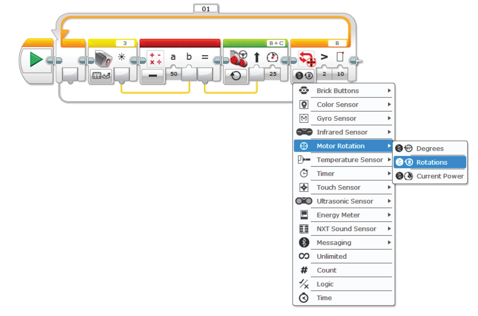
Configure the Color Sensor for Measure -> Reflected Intensity. Set the Math Block to Subtract and type 50 for the value of "a". Set the Move Steering Block to ON and the Loop Block to Motor Rotations -> Rotations and Greater than (>) and set the limit to 10.


How it Works
First, the Color Sensor returns a number indicating the average brightness of the area illuminated by the internal LED (the sensor returns 0 for all black, 100 for all white and 50 if halfway between black and white). Then the Math Block takes our set point (50 when the Color Sensor is centered on the edge of the line) and subtracts the Color Sensor reading. The result of that calculation is the system Error. Next the Error is applied to set the Steering input of the Mover Steering block. We set the Power to 25 on the Move Steering block. Finally, the Loop block runs the from the time you start the program until the B motor has turned for more than 10 rotations.Some examples. We can see that when the Color Sensor is over the edge of the line, the measured value is 50. We calculate the Error with the Math Block, Error = Set Point (50) - Measured Value (50) = 0. So our Error is 0 and the Steering input is set to 0, telling the robot to drive straight and the robot stays on the edge of the line.
If the Color Sensor drifts to the right, away from the black line toward the white background, the Color Sensor will return a higher number, for example 60. The Math Block calculates: Error = Setpoint(50) - Measured Value (60) = -10. So the Error is -10 and the Steering input is set to -10 or run the left motor 10 percent slower than the right motor, turning the robot left toward the black line. The opposite happens if the robot drifts left and the sensor is more over the black line and returns a lower number.
Place your robot so that the light sensor is on the right edge of the black line. Then have your robot try to follow the line and see how it does. If the robot runs off of the line, turn the robot around and have it follow the line in the other direction (your robot may do better for left turns or right turns so give each a try). If your Color Sensor is mounted off-center the robot will need a different gain for turning left and turning right. That approach is called asymmetrical gain and is common in temperature control systems that may heat and cool at different rates. We will discuss using a Switch Block to apply asymmetrical gain at a later date.
Behind the Curtain
Note that we are using some shortcuts in this simple implementation. First we count on the Color Sensor being calibrated, allowing us to use 50 as our setpoint or target value. You can use the same program with an uncalibrated Color Sensor but you must look at the values returned from the sensor for all black and all white and select a target value halfway between those two values. We found an uncalibrated NXT sensor that returned 36 for white and 6 for black. So we would use a target value of 21 (halfway between 6 and 36).The program also never actually multiplies our Error by a gain. We just use the Error as is, so there was an implicit multiplication by a gain of one. This works because our expected Error range from the calibrated sensor is -50 to +50 which maps well into a Steering input for the Move Steering block. If you use an uncalibrated sensor you are likely to get a smaller range of numbers that does not map as well to Steering Angle. For our uncalibrated example the Error would range from -15 (21-36) to +15 (21-6). This Error range is much lower than that seen from our calibrated sensor and may not be enough change to steer the robot back on track. So you may need to a gain of 50/15 or around 3.3 to give the same steering feedback over the Error range as a calibrated sensor. This can be done by multiplying the output of the uncalibrated sensor by 3.3 using a Math Block.
Moving Forward (Advanced Exercises)
A good next step after you have the line follower working with a calibrated sensor is to reset your calibration and get the program to work with the uncalibrated sensor. You will need to select the mid-point between black and white for your target value and calculate a gain to scale your maximum and minimum reflected light values to 50 and -50 respectively. This is a great time to use your EV3's Port View to look at the sensor value when you move the sensor back and forth between the white board and the center of the black line. When you are finished remember to calibrate your sensor for future use.Next add a math multiply block (or select ADV on your error calculation block) to multiply your error by a gain and test the robot with lower and lower gain until the robot fails to follow the line. How did the robot behave? Now increase the gain until the robot fails to follow the line. How did the high gain failure look different from the low gain failure? Try different motor powers and adjust the gain. You may find that the robot moves more smoothly with different gains at different speeds.
Try adding new features. How about lighting up the EV3 front panel in one color for a left turn and another color for a right turn? Or add an Ultrasonic Sensor pointing straight up and program the robot so you can move your hand closer to the top of the robot to make it drive faster. How about making the robot automatically drive faster when the error value is low (which means the robot is driving straight or almost straight).
Or you could replace the Color Sensor with a Gyro Sensor in Angle Mode and create a robot that will drive straight, even if the wheels slip or gets nudged. Be sure to have the robot setting on the floor when you power up the robot to ensure the Gyro Sensor starts up with no drift (look at the Gyro Sensor in Port View and make sure the value is stable when the robot is setting still). If the Gyro Sensor is drifting you can un-plug and reconnect the sensor's cable or restart the EV3. The number for "a" in the Math Block following the sensor sets the heading. Modify the program to have the robot drive straight in the direction the robot is pointing when you start the program.
I hope this has helped you understand how a proportional line follower works on the LEGO EV3 platform and how this simple approach can be used as a starting point for further exploration of using proportional control.
No comments:
Post a Comment